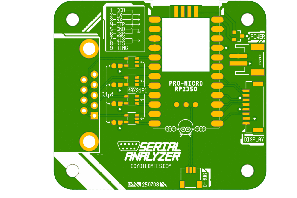
The main board contains the core components of Serial Analyzer.
Microcontroller
The brain of the Main Board is the Pro Micro RP2350 by SparkFun. This board was chosen for its compact size, 16 MB of flash, 8 MB of PSRAM, and the lack of a LiPo charging circuit. The RP2350 itself provides two cores clocked at 150 MHz, which is more than enough for a rich user interface and processing for analyzing RS-232 signals.
DB9 Female Connector
The DB9 connector is used to connect to the device under test. The signals are connected as follows:
- The TX pin connects to a MAX3181.
- The RX pin connects to a MAX3181.
- The DTR, DSR, and DCD pins are tied together and connect to a MAX3181.
- The RTS and CTS pins are tied together and connect to a MAX3181.
- The Ground pin is connected to the board ground.
- The Ring pin is left disconnected.

MAX3181 Receivers
The main board contains four MAX3181 RS-232 to TTL receivers. Each receiver can input a single RS-232 signal and output a TTL signal and an Invalid signal. The Invalid signal is crucial for detecting cable connection and the presence of certain lines.
Power
Board power is provided through the SparkFun Pro Micro RP2350’s USB-C connector, or through the 2-pin JST connector on the main board. A P-MOSFET is used to safely handle simultaneously connected power sources.
I2C
The keyboard is connected by an I2C bus through the SparkFun Pro Micro RP2350’s onboard QWIIC connector. The nature of the I2C bus allows additional peripherals to be added using the same connector.
SPI
The main board connects to a display through an SPI connector. While there is no standardized SPI connector, an 8-bit connector was chosen to provide sufficient signals to the display.
Debug
A debug connector was also added for development and troubleshooting.